Showing posts with label Technology. Show all posts

Sunday, June 17, 2018

Memory Organization in Computer Architecture

A memory unit is the collection of storage units or devices together. The memory unit stores the binary information in the form of bits. Generally, memory/storage is classified into 2 categories:
Volatile Memory: This loses its data, when power is switched off.
Non-Volatile Memory: This is a permanent storage and does not lose any data when power is switched off.

Memory Hierarchy
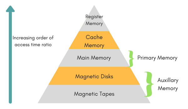


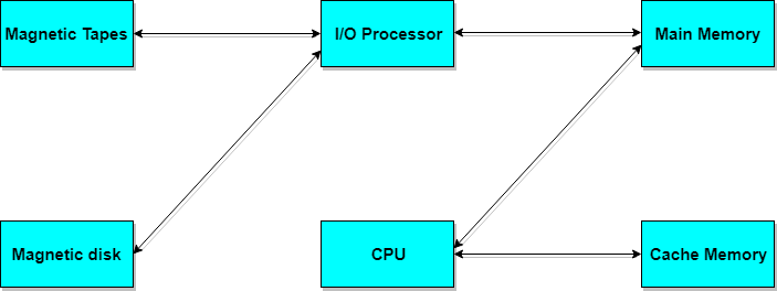
The total memory capacity of a computer can be visualized by hierarchy of components. The memory hierarchy system consists of all storage devices contained in a computer system from the slow Auxiliary Memory to fast Main Memory and to smaller Cache memory.

Auxillary memory access time is generally 1000 times that of the main memory, hence it is at the bottom of the hierarchy.

The main memory occupies the central position because it is equipped to communicate directly with the CPU and with auxiliary memory devices through Input/output processor (I/O).

When the program not residing in main memory is needed by the CPU, they are brought in from auxiliary memory. Programs not currently needed in main memory are transferred into auxiliary memory to provide space in main memory for other programs that are currently in use.

The cache memory is used to store program data which is currently being executed in the CPU. Approximate access time ratio between cache memory and main memory is about 1 to 7~10


Memory Access Methods

Each memory type, is a collection of numerous memory locations. To access data from any memory, first it must be located and then the data is read from the memory location. Following are the methods to access information from memory locations:
Random Access: Main memories are random access memories, in which each memory location has a unique address. Using this unique address any memory location can be reached in the same amount of time in any order.
Sequential Access: This methods allows memory access in a sequence or in order.
Direct Access: In this mode, information is stored in tracks, with each track having a separate read/write head.


Main Memory

The memory unit that communicates directly within the CPU, Auxillary memory and Cache memory, is called main memory. It is the central storage unit of the computer system. It is a large and fast memory used to store data during computer operations. Main memory is made up of RAM and ROM, with RAM integrated circuit chips holing the major share.
- RAM: Random Access Memory
- DRAM: Dynamic RAM, is made of capacitors and transistors, and must be refreshed every 10~100 ms. It is slower and cheaper than SRAM.
- SRAM: Static RAM, has a six transistor circuit in each cell and retains data, until powered off.
- NVRAM: Non-Volatile RAM, retains its data, even when turned off. Example: Flash memory.
- ROM: Read Only Memory, is non-volatile and is more like a permanent storage for information. It also stores the bootstrap loader program, to load and start the operating system when computer is turned on. PROM(Programmable ROM), EPROM(Erasable PROM) and EEPROM(Electrically Erasable PROM) are some commonly used ROMs.


Auxiliary Memory

Devices that provide backup storage are called auxiliary memory. For example: Magnetic disks and tapes are commonly used auxiliary devices. Other devices used as auxiliary memory are magnetic drums, magnetic bubble memory and optical disks.

It is not directly accessible to the CPU, and is accessed using the Input/Output channels.


Cache Memory


The data or contents of the main memory that are used again and again by CPU, are stored in the cache memory so that we can easily access that data in shorter time.

Whenever the CPU needs to access memory, it first checks the cache memory. If the data is not found in cache memory then the CPU moves onto the main memory. It also transfers block of recent data into the cache and keeps on deleting the old data in cache to accomodate the new one.


Hit Ratio

The performance of cache memory is measured in terms of a quantity called hit ratio. When the CPU refers to memory and finds the word in cache it is said to produce a hit. If the word is not found in cache, it is in main memory then it counts as a miss.

The ratio of the number of hits to the total CPU references to memory is called hit ratio.

Hit Ratio = Hit/(Hit + Miss)

Associative Memory

It is also known as content addressable memory (CAM). It is a memory chip in which each bit position can be compared. In this the content is compared in each bit cell which allows very fast table lookup. Since the entire chip can be compared, contents are randomly stored without considering addressing scheme. These chips have less storage capacity than regular memory chips.

The TCP/IP Reference Model

TCP/IP means Transmission Control Protocol and Internet Protocol. It is the network model used in the current Internet architecture as well. Protocols are set of rules which govern every possible communication over a network. These protocols describe the movement of data between the source and destination or the internet. They also offer simple naming and addressing schemes.


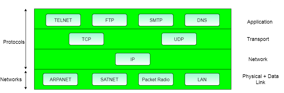
Protocols and networks in the TCP/IP model:


Overview of TCP/IP reference model

TCP/IP that is Transmission Control Protocol and Internet Protocol was developed by Department of Defence's Project Research Agency (ARPA, later DARPA) as a part of a research project of network interconnection to connect remote machines.

The features that stood out during the research, which led to making the TCP/IP reference model were:
Support for a flexible architecture. Adding more machines to a network was easy.
The network was robust, and connections remained intact untill the source and destination machines were functioning.

The overall idea was to allow one application on one computer to talk to(send data packets) another application running on different computer.

Different Layers of TCP/IP Reference Model

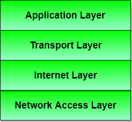
Below we have discussed the 4 layers that form the TCP/IP reference model:


Layer 1: Host-to-network Layer

Lowest layer of the all.
Protocol is used to connect to the host, so that the packets can be sent over it.
Varies from host to host and network to network.

Layer 2: Internet layer

Selection of a packet switching network which is based on a connectionless internetwork layer is called a internet layer.
It is the layer which holds the whole architecture together.
It helps the packet to travel independently to the destination.
Order in which packets are received is different from the way they are sent.
IP (Internet Protocol) is used in this layer.

The various functions performed by the Internet Layer are:
- Delivering IP packets
- Performing routing
- Avoiding congestion

Layer 3: Transport Layer

It decides if data transmission should be on parallel path or single path.
Functions such as multiplexing, segmenting or splitting on the data is done by transport layer.
The applications can read and write to the transport layer.
Transport layer adds header information to the data.
Transport layer breaks the message (data) into small units so that they are handled more efficiently by the network layer.
Transport layer also arrange the packets to be sent, in sequence.

Layer 4: Application Layer

The TCP/IP specifications described a lot of applications that were at the top of the protocol stack. Some of them were TELNET, FTP, SMTP, DNS etc.
TELNET is a two-way communication protocol which allows connecting to a remote machine and run applications on it.
FTP(File Transfer Protocol) is a protocol, that allows File transfer amongst computer users connected over a network. It is reliable, simple and efficient.
SMTP(Simple Mail Transport Protocol) is a protocol, which is used to transport electronic mail between a source and destination, directed via a route.
DNS(Domain Name Server) resolves an IP address into a textual address for Hosts connected over a network.
It allows peer entities to carry conversation.
It defines two end-to-end protocols: TCP and UDP
TCP(Transmission Control Protocol): It is a reliable connection-oriented protocol which handles byte-stream from source to destination without error and flow control.
UDP(User-Datagram Protocol): It is an unreliable connection-less protocol that do not want TCPs, sequencing and flow control. Eg: One-shot request-reply kind of service.

Transmission Modes in Computer Networks

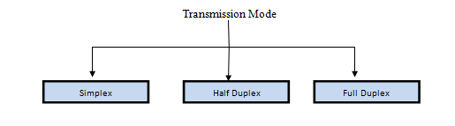
Transmission mode refers to the mechanism of transferring of data between two devices connected over a network. It is also called Communication Mode. These modes direct the direction of flow of information. There are three types of transmission modes. They are:
- Simplex Mode
- Half duplex Mode
- Full duplex Mode


SIMPLEX Mode

In this type of transmission mode, data can be sent only in one direction i.e. communication is unidirectional. We cannot send a message back to the sender. Unidirectional communication is done in Simplex Systems where we just need to send a command/signal, and do not expect any response back.

Examples of simplex Mode are loudspeakers, television broadcasting, television and remote, keyboard and monitor etc.


HALF DUPLEX Mode

Half-duplex data transmission means that data can be transmitted in both directions on a signal carrier, but not at the same time.

For example, on a local area network using a technology that has half-duplex transmission, one workstation can send data on the line and then immediately receive data on the line from the same direction in which data was just transmitted. Hence half-duplex transmission implies a bidirectional line (one that can carry data in both directions) but data can be sent in only one direction at a time.

Example of half duplex is a walkie- talkie in which message is sent one at a time but messages are sent in both the directions.


FULL DUPLEX Mode

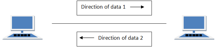
In full duplex system we can send data in both the directions as it is bidirectional at the same time in other words, data can be sent in both directions simultaneously.

Example of Full Duplex is a Telephone Network in which there is communication between two persons by a telephone line, using which both can talk and listen at the same time.


In full duplex system there can be two lines one for sending the data and the other for receiving data.

The OSI Model - Features, Principles and Layers

There are n numbers of users who use computer network and are located over the world. So to ensure, national and worldwide data communication, systems must be developed which are compatible to communicate with each other ISO has developed a standard. ISO stands for International organization of Standardization. This is called a model for Open System Interconnection (OSI) and is commonly known as OSI model.

The ISO-OSI model is a seven layer architecture. It defines seven layers or levels in a complete communication system. They are:
7.Application Layer
6.Presentation Layer
5.Session Layer
4.Transport Layer
3.Network Layer
2.Datalink Layer
1.Physical Layer

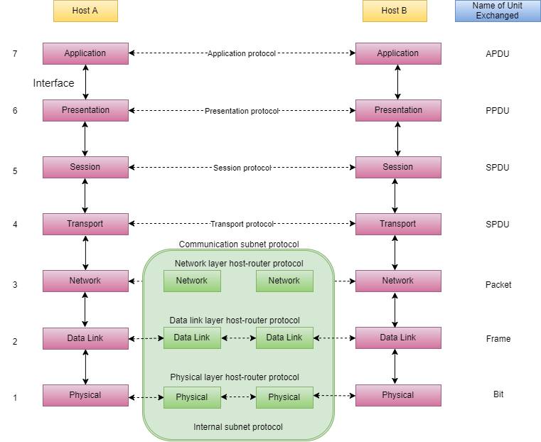
Below we have the complete representation of the OSI model, showcasing all the layers and how they communicate with each other.


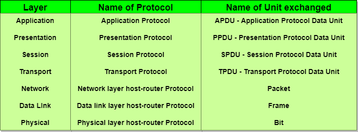
In the table below, we have specified the protocols used and the data unit exchanged by each layer of the OSI Model.


Feature of OSI Model

Big picture of communication over network is understandable through this OSI model.
We see how hardware and software work together.
We can understand new technologies as they are developed.
Troubleshooting is easier by separate networks.
Can be used to compare basic functional relationships on different networks.
Principles of OSI Reference Model

Types of Network Topology

Network Topology is the schematic description of a network arrangement, connecting various nodes(sender and receiver) through lines of connection.
BUS Topology

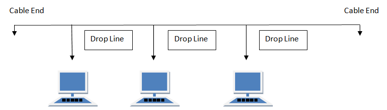
Bus topology is a network type in which every computer and network device is connected to single cable. When it has exactly two endpoints, then it is called Linear Bus topology.


Features of Bus Topology

- It transmits data only in one direction.
- Every device is connected to a single cable

Advantages of Bus Topology

It is cost effective.
Cable required is least compared to other network topology.
Used in small networks.
It is easy to understand.
Easy to expand joining two cables together.

Disadvantages of Bus Topology

Cables fails then whole network fails.
If network traffic is heavy or nodes are more the performance of the network decreases.
Cable has a limited length.
It is slower than the ring topology.


RING Topology

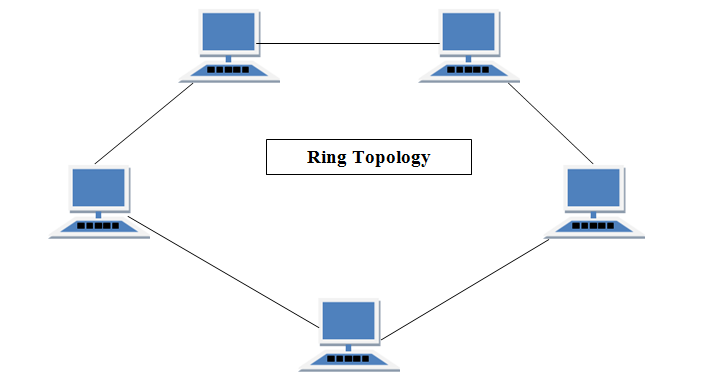
It is called ring topology because it forms a ring as each computer is connected to another computer, with the last one connected to the first. Exactly two neighbours for each device.


Features of Ring Topology

A number of repeaters are used for Ring topology with large number of nodes, because if someone wants to send some data to the last node in the ring topology with 100 nodes, then the data will have to pass through 99 nodes to reach the 100th node. Hence to prevent data loss repeaters are used in the network.
The transmission is unidirectional, but it can be made bidirectional by having 2 connections between each Network Node, it is called Dual Ring Topology.
In Dual Ring Topology, two ring networks are formed, and data flow is in opposite direction in them. Also, if one ring fails, the second ring can act as a backup, to keep the network up.
Data is transferred in a sequential manner that is bit by bit. Data transmitted, has to pass through each node of the network, till the destination node.

Advantages of Ring Topology

Transmitting network is not affected by high traffic or by adding more nodes, as only the nodes having tokens can transmit data.
Cheap to install and expand

Disadvantages of Ring Topology

Troubleshooting is difficult in ring topology.
Adding or deleting the computers disturbs the network activity.
Failure of one computer disturbs the whole network.


STAR Topology

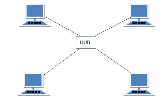
In this type of topology all the computers are connected to a single hub through a cable. This hub is the central node and all others nodes are connected to the central node.


Features of Star Topology

Every node has its own dedicated connection to the hub.
Hub acts as a repeater for data flow.
Can be used with twisted pair, Optical Fibre or coaxial cable.

Advantages of Star Topology

Fast performance with few nodes and low network traffic.
Hub can be upgraded easily.
Easy to troubleshoot.
Easy to setup and modify.
Only that node is affected which has failed, rest of the nodes can work smoothly.

Disadvantages of Star Topology

Cost of installation is high.
Expensive to use.
If the hub fails then the whole network is stopped because all the nodes depend on the hub.
Performance is based on the hub that is it depends on its capacity


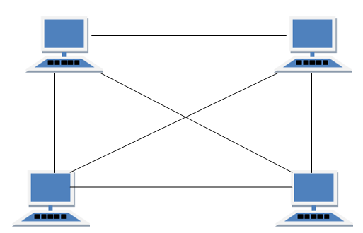
MESH Topology

It is a point-to-point connection to other nodes or devices. All the network nodes are connected to each other. Mesh has n(n-1)/2 physical channels to link n devices.

There are two techniques to transmit data over the Mesh topology, they are :
Routing
Flooding

MESH Topology: Routing


In routing, the nodes have a routing logic, as per the network requirements. Like routing logic to direct the data to reach the destination using the shortest distance. Or, routing logic which has information about the broken links, and it avoids those node etc. We can even have routing logic, to re-configure the failed nodes.

MESH Topology: Flooding

In flooding, the same data is transmitted to all the network nodes, hence no routing logic is required. The network is robust, and the its very unlikely to lose the data. But it leads to unwanted load over the network.


Types of Mesh Topology

Partial Mesh Topology : In this topology some of the systems are connected in the same fashion as mesh topology but some devices are only connected to two or three devices.
Full Mesh Topology : Each and every nodes or devices are connected to each other.
Features of Mesh Topology
Fully connected.
Robust.
Not flexible.
Advantages of Mesh Topology
Each connection can carry its own data load.
It is robust.
Fault is diagnosed easily.
Provides security and privacy.

Disadvantages of Mesh Topology

Installation and configuration is difficult.
Cabling cost is more.
Bulk wiring is required.


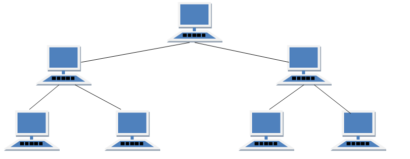
TREE Topology

It has a root node and all other nodes are connected to it forming a hierarchy. It is also called hierarchical topology. It should at least have three levels to the hierarchy.


Features of Tree Topology

Ideal if workstations are located in groups.
Used in Wide Area Network.

Advantages of Tree Topology

Extension of bus and star topologies.
Expansion of nodes is possible and easy.
Easily managed and maintained.
Error detection is easily done.

Disadvantages of Tree Topology
Heavily cabled.
Costly.
If more nodes are added maintenance is difficult.
Central hub fails, network fails.


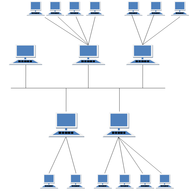
HYBRID Topology

It is two different types of topologies which is a mixture of two or more topologies. For example if in an office in one department ring topology is used and in another star topology is used, connecting these topologies will result in Hybrid Topology (ring topology and star topology).


Features of Hybrid Topology

It is a combination of two or topologies
Inherits the advantages and disadvantages of the topologies included

Advantages of Hybrid Topology

Reliable as Error detecting and trouble shooting is easy.
Effective.
Scalable as size can be increased easily.
Flexible.

Disadvantages of Hybrid Topology
Complex in design.
Costly.
Back to Top